Introduction
In the article, I compact several relevant projects about the system and control method.
Technical Objective
The article can be separated into two phrases. The first stage is the system identification with which to achieve valid parameters of a DC motor in real world. The second stage is to design the controller for the DC motor according to the parameters. All of stages are applied to real-time Simulink in Matlab.
Hardware and environment
Equipment for Real-time Simulink
A host computer, a target computer, a PCI 6024e board, NI CB-68LP board, DC driver as shown in Figure below
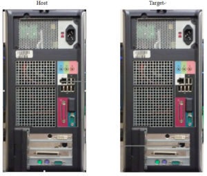
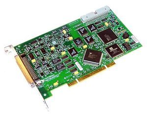
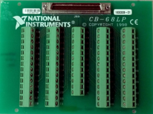
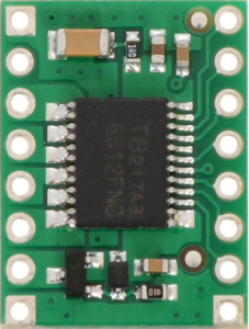
For real-time Simulink, installation is subtly complex, its reference to Mathwork online. I also record my configuration in my word document. Finally,target monitor shows the figure 1.
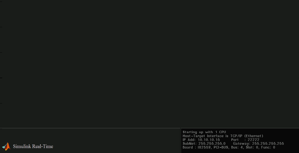
Figure 1 Target monitor
Test XPC
Connect NI CB-68LP board to NI PCI 6024E on the target computer over a cable, wire 22 terminal ( AO 0) to 34 terminal (AI 8) on the NI CB-68LP board,and run a simple program as shown below
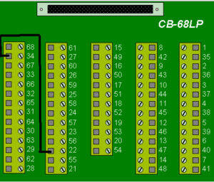
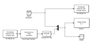
Setup a sinusoid in signal generator and the right input and output port, configure to the real-time Simulink mode, and the right data on target monitor shows in figure 2

Figure 2 Test result on target monitor
Peripheral Hardware
It consists of Motor drive scheme, a motor driver datasheet, motor encoder pinout, NI-Encoder.
Scheme of the NI CB-68LP board, motor driver, motor
Signal is generated by the real-time Simulink through the NI CB-68LP board and goes to the motor driver to motor. It feedbacks the position and velocity with the motor encoder, and current of the motor in the figure 3.

Figure 3 Connection of motor, motor driver, encoder, NI CB-68LP,
Programmation
system Identification
Setup PRBS (Pseudo Random Binary Sequence) in the signal generator, which are always in the experimental approach for system identification. Feedback primary impulses from an encoder of the DC motor and manipulate it to the position and velocity of the motor with accumulator and derivative. The scheme in figure 4. Download the code

Figure 4 Collection data for system identification
.
System identification with toolbox
I use system identification toolbox in Matlab to achieve the parameters of the motor mode with the code of system identification .
So I have the model parameters of the DC motor
\(A=\begin{bmatrix} 0 & 1 \\ 0 & -5.643 \end{bmatrix}\)
\(B=\left[ \begin{matrix} 0 \\ 50.83 \end{matrix} \right] \)
\(C=\left[ \begin{matrix} 1 & 0 \\ 0 & 1 \end{matrix} \right]\)
\(D=\left[ \begin{matrix} 0 \\ 0 \end{matrix} \right]\)
An alternative method is to use GUI system identification, You can read Matlab system identification toolbox to know more detail.
Until now I finish the system identification of the DC motor, and get the state-space to design the controller for next stage.
POSITION CONTROL shows the Simulink in figure 5 and the LQR code to position

Figure 5 LQR for position
Position track of DC motor

Figure Tracking position of motor
Velocity CONTROL shows the Simulink in figure 6 and the code to velocity
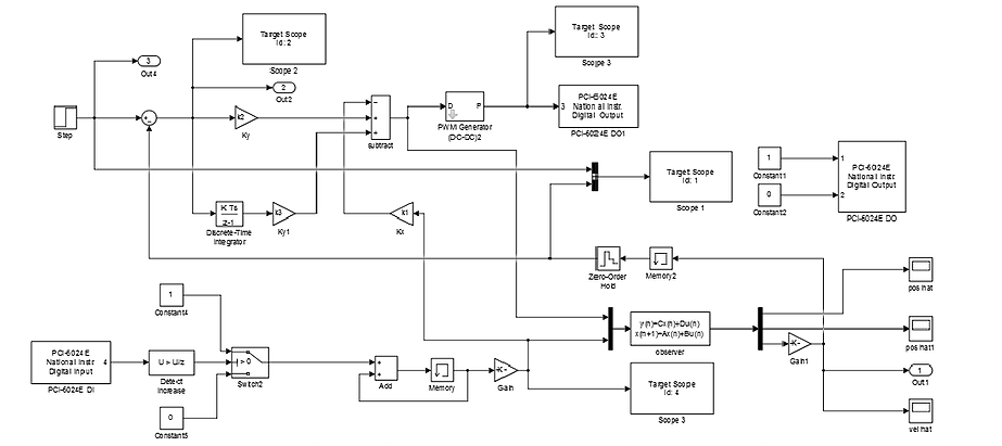
Figure 6 LQR for velocity
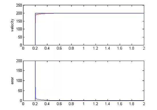
Velocity track of DC motor
