AVR Timer-CTC Mode

Introduction

In the article, I wanted to integrate MEMS microphones and AtTmega 328p together to sample the audio signals, and its tech refers to cover timer,  serial communication, and lowpass filter. Due to the time, I only write the first portion of configuring a timer. I will proceed with the serial communication and lowpass filter later.

Hardware

Using a PDM microphone (IM69D130) in this project. This microphone, which is connected with a 1 Mhz clock, can generate a  stream of bit signal, and I truncate it with a register and check the signal with an oscilloscope. The connection of Arduino UNO and microphone shows in Figure below. 

Figure connection of arduino and microphone

Timer

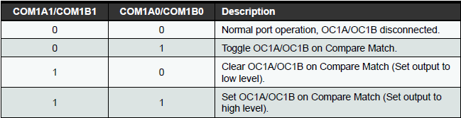
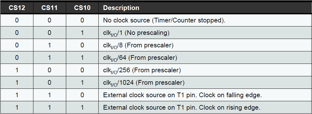
Timers are used everywhere in the field of electronics today. I configure a 16-bit timer in ATmega 328P with the prescaler, CTC mode, toggle OC1A on compare match. 
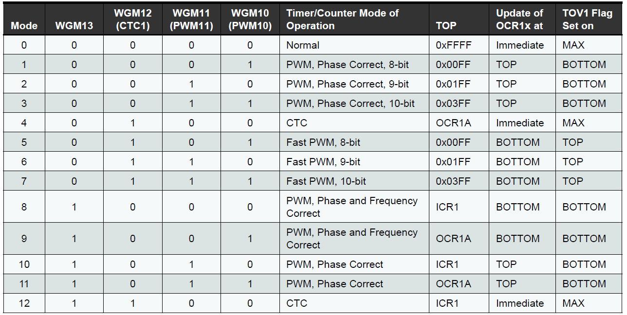
CTC Mode

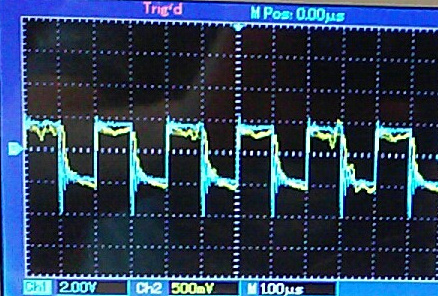
Through formula \(Timer\quad Count=\frac { required\quad delay }{ clock\quad time\quad period } -1\) ,  given a prescaler of 1 and MCU 16 Mhz, setup the timer count as 15 to get 1 Mhz clock. 

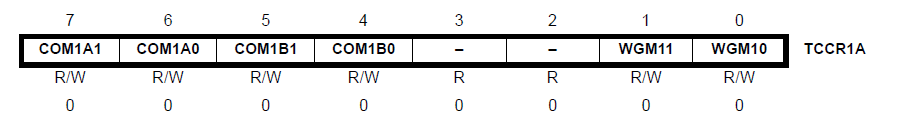
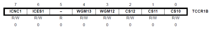
TCCR1A and TTCR1B register show in the below

Digital 9 pin outputs the 1 MHz clock that wires to the microphone clock portal.   The Arduino UNO datasheet                 ATmega 328p Timer

The date is shown on the oscilloscope. The blue is the timer counter, the yellow is the signal of the microphone

Figure signal and timer

Conclusion

The left work is to truncate the sample out of stream through serial communication and design a lowpass filter.