
Background
Florida Institute of Technology collabrated with Orbital ATK to improve tanks for satellites and more precisely the propellant management devices. Propellant management devices are located within the propellant tanks of spacecraft and satellites operating in a micro-gravity environment. In the micro-gravity environment, special considerations of effects on the fluid must be taken into account when designing a unique propellant management device for each mission and propellant combination. To improve the injection of the gas in the tank, the company is designing special tanks and propellant management devices and for that, they need some special characteristics and behavior of a gas in contact with the tank. Orbital ATK asked the FIT to measure these characteristics.
Adrien Jasinski and I worked to reconfigure the machine which was built by FIT for the measurement of properties of a droplet.
Technical objective
a.general purpose
The project is called Estimation of Contact Angle and Surface Tension; the goal is to measure two properties on a droplet of a gas to test. These measures will be used by orbital ATK to design propellant management devices.
CONTACT ANGLE
The first property to measure is the contact angle. This property is a quantification of a liquid’s wettability. Wettability describes the ability of a liquid to adhere to and disperse itself on a solid surface. The contact angle is inversely proportional to wettability, as the contact angle increases from 0 degrees (perfectly wetting) to 180 degrees (non-wetting) as shown in Figure 1

Figure 1 Wettability as a function of contract angle
Direct contact angle measurements are susceptible to hysteresis, which are dependent on the surface roughness of the solid interface. To quantify contact angle hysteresis, we need to measure two other contact angles: the advancing and receding contact angles. The difference between these two angles is the hysteresis. These two angles can be directly measured by varying the solid surface angle respecting the horizontal.
SURFACE TENSION
The method to determine surface tension of a liquid is called the Fynn Knut Hansen’s method. First, a droplet picture of the liquid is taken with a reference reticule in place, and then the droplet edges are measured with the software vision assistant.

Figure 2 Estimation of surface tension through Finn Knut Hansen Method
With the two measurements DS and DE it is possible to compute the surface tension of the liquid.
\(\gamma =\frac { \triangle \rho g{ R }_{ 0 }^{ 2 } }{ \beta } \)
\(\beta =-0.12836+0.7577\sigma -1.7713{ \sigma }^{ 2 }+0.5426{ \sigma }^{ 3 }\)
\({ R }_{ 0 }=\frac { { D }_{ E } }{ 2(0.9987-0.1971\beta -0.0734{ \beta }^{ 2 }-0.34708{ \beta }^{ 3 }) }\)
\(\sigma ={ { D }_{ S } }/{ { D }_{ E } }\)
where γ is the surface tension of the liquid in N/m, Δρ is the change in mass density between the liquid and vapor mediums respectively ρ2-ρ1 in kg/m3, g is the force due to gravity in m/s2, R0 is the radius of curvature at drop apex in m, β is a dimensionless shape factor, σ is the dimensionless diameter ratio, DE is the maximum diameter of a pendant droplet in m, and DS is the diameter at the distance DE from the drop apex in m.
b.Hardware
With a machine built by the FIT, we can measure these properties. The whole machine is controlled by a computer with the software LabVIEW. The machine can inject a droplet with a needle on a titanium plate, take a picture of it and then rotate the plate in order to take a picture of the receiving and advancing angle. In order to realize measurements for exotic gas for spacecraft, it is important to respect the operating pressure and temperature. For that, the titanium plate is in a pressure chamber and the pressure and temperature can be chosen. The entire chamber can be rotated +/- 90 degrees.
This machine was moved into a cold chamber a few months ago and after the relocation of the equipment on the machine it was not working properly. As a matter of fact, after moving it a lot of wires were disconnected and the connection between the computer and the machine was not working. Our work was to re-connect every component of the machine with the computer. Most of the components of the machine have a TCP-IP communication with Ethernet wires.
The system uses two Basler Ace 5 megapixel Gig-E Ethernet cameras in Figure 3. We installed the first camera to monitor the status of the entire experiment (Figure 20). The camera is mounted inside the cooling unit. This camera allows the operator to visually observe the system’s operation from a safe distance.

Figure 3 Basler Ace equipped with wide angle lens
A second camera is secured to a two-axis micrometer stage on the rotating cage section of the platform. The camera is positioned such that it can directly observe the test specimen and any droplet applied to it.
The rotating cage undergoes angular positioning through a servo motor-drive in Figure 4. This system uses a ”Cool-Muscle” motor drive, which incorporates encoder and current feedback with a controller. The motor drive is equipped with an Ethernet connection, allowing position commands to be sent over TCP/IP. The ”Cool-Muscle” comes with the program ”Control Room” to tune and set the parameters of the controller via the TCP/IP link.

Figure 4 Cool muscle Servo Motor
To set the zero angle (perfectly horizontal), a tri-axial DC response micro-electromechanical system, accelerometer is used. The sensor outputs a voltage proportional to acceleration, which the control PC acquires. Because the micro-electromechanical system was damaged we added a bubble level to make the zero angle manually. The droplet machine shows in Figure 5.
When the zero angle is done the measurement from the micro-electromechanical system is the difference to take into account to obtain the right measurement.

Figure 5 The droplet machine
c.Software
FESTO
Festo’s proprietary software, FCT, enables effortless configuration of the actuator by using component hardware profiles. The software also enables the user to manually input both complex motion profiles and simple point-to-point commands. In our case, we only used point-to-point commands.
LABVIEW
The LabView program brings together all the instruments and devices into a friendly graphical user interface. The front panel, shown in Figure 6, provides both indicators and controls for the system. In addition to simply displaying data, the program is set to capture and save instrument data with the touch of the ”Grab and Save” button.
Our main problems to solve on this program were about connections and about the quality of the image obtained from the two cameras.
As you can see in figure 6 some black lines appear on the screen, the issue with the black lines is most likely due to a lack of bandwidth resulting in packets from the camera being dropped. The missing packets will appear as black lines in the image. First, we looked at the settings for the network card and we set up properly then we changed the performance of the TCP/IP connection of the computer cardboard.
The quality is now better and the black lines appear only for a few seconds and disappear a few seconds after so it is possible to take a good picture of the droplet without black lines.

Figure 6 Front panel of the LabView program
VISION ASSISTANT
The edge detection and image processing are done in Vision Assistant, the tool called “Detect a Straight Edge” can detect and measure the contact angle of the droplet as it’s possible to see in figure 7.
To measure DE and DS we used the tool measure: It can measure the number of pixels. Then the conversion in the meter is made possible by using a reference reticule in place. In our case, we could use the diameter of the needle.
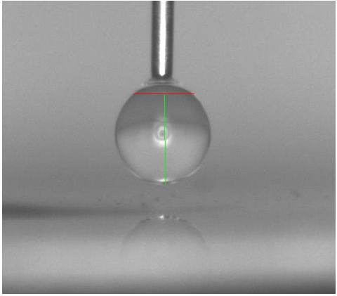
Figure 7 Length measurement of De and Ds on Vision assistant
We made some measurements with water to test the proper functioning of the machine, the injection of the water worked well but because the diameter of the needle installed in the machine was unknown it was not possible to monitor the conversion from pixel to meter and consequently to monitor the surface tension. Without documentation on it, the only way to know the diameter of the needle was to open entirely the machine and extract the needle.
Test procedure
Because we spent a lot of time to understand the operation of the machine we decided to write a test procedure to use it. The next user should be able to use the machine and do measurements quicker.
For this first step, The Labview program and every other software should not run:
- Place the machine at 90° by hand

- Open the bottom part and extract the part with the titanium plate, clean up the titanium plate:

Before closing the bottom part:
Launch the software FCT, push red button offline to online (it will become green)
Go to manual mode (menu at the bottom), in device control choose FCT then sync, then
- push out all the “old” liquid in the Festo (left side)
- Fill all the syringe with the new liquid (right)
- push out the liquid of the syringe (left) slowly until the first droplet appear and clean the area where the droplet falls
Then you can close the bottom part
- Adjust the machine perfectly horizontal at a 0° angle. For that run the program LabView and adjust the angle motor by using the bubble level (the accelerometer does not give zero at a zero angle). If the motor does not run, stop the program, unplug and replug the main power on the motor and start again.
- NB: The machine should be perfectly horizontal with the values -3.9 on the accelerometer so an angle selected of 2.45°
- send a droplet with FCT (left side) and grab the image.
Conclusion
It is controversial to define where it is the starting-point to measure the angle which will be left for others in the future.